A split Hopkinson pressure bar (SHPB), is a test apparatus used to characterize the mechanical response of materials deforming at high strain rates (102 – 104 s-1). Comparison of strain rate regimes for SHPB to some other classes of testing facilities, the SHPB has evolved from the original version of dynamic compression loading to various versions of other loading states, including tension, torsion, triaxial and axial/shear combination. The principles for all these methods are similar. The major differences are in loading mechanisms and specimen gripping methods.
Although there are various setups and techniques currently in use for the Split-Hopkinson pressure bar, the underlying principles for the test and measurement are the same. The specimen is placed between the ends of two straight bars, called the incident bar and the transmitted bar. At the end of the incident bar, a stress wave is created which propagates through the bar toward the specimen. This wave is referred to as the incident wave, and upon reaching the specimen, splits into two smaller waves. One of which, the transmitted wave, travels through the specimen and into the transmitted bar, causing plastic deformation in the specimen. The other wave, called the reflected wave, is reflected away from the specimen and travels back down the incident bar. Strains caused by the waves are measured using strain gauges on the bars. Then the stress and strain can be calculated from the amplitudes of the incident, transmitted, and reflected waves based on the assumption that the deformation in the specimen is uniform.

SHPB Components
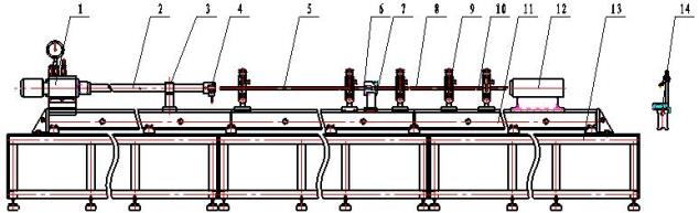
- Gas emitter
- Launcher tube
- Launcher tube support
- Speed sensor
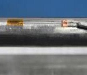
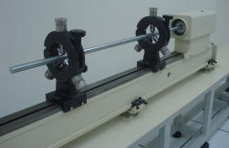
- Incident bar
- Universal head for calibration purpose
- Test specimen protection box
|
- Transmission bar
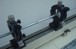
- Center bearing bracket
- Momentum bar
- Guide rail
- Cushion buffer
- Steel base
- Leveling gauge
|
The system shown is a generic compression type.
Technical specification:
- Gas tank capacity: 0.08 m³
- Emitter working pressure range: 0 – 5 MPa (0 – 730 psi)
- Emitter: length 2 m; inner diameter: Ø20 mm
- Striker bar speed range: ≤ 50 m/s
- Striker bar diameter: Ø20
- Striker bar length: 200, 400, 500 mm
- Bars material: High strength alloy steel, heat treated, yield strength of ≥ 1500MPa, the straightness of 0.08/m, end surface perpendicularity ≤ 0.02, the surface roughness ≤ 0.8μm
|
System Variant:
- Type of Loading – Compression, Tension or Torsion
- Construction Material
- Total length of system
- Size (length and diameter) of bar system
- Size of Striker
- Launcher pressure range requirement
- Type and construction of strain gauge
- Momentum Trap Inclusion
- Data Acquisition System Inclusion
|
Functional Sections
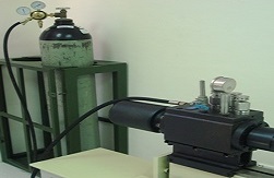 |
Driving Section
Using the compressed gas, with the pressure vessel containing emission gas pressurized at 0.8-5 MPa. The operating system is provided with a pressure fine-tune structure and control system. Projectile velocity up to 50 ms-1 and is readily customizable to higher values. |
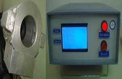 |
Speed measurement
The velocity of the striker bar is measured using optical sensors, with the digital display gives the reading in m/s up to 4 decimal places. |
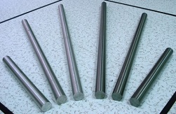 |
Bar system
Bars made of heat treated high strength alloy steel with yield strength ≥ 1500 MPa and super-hard aluminum with yield strength ≥ 400 MPa. Other materials include high strength spring steel, 18% Ni steel and polymers. Diameter ranging from 8 mm to 100 mm. Other sizes can be custom-made. The inner diameter of the launch tube is 20 mm, with effective length not less than 2m, equipped with coupling structure to the gas emission structure and the support structure. |
 |
Centre supporting and aligning devices
Constructed of a fixed base, opening upper bracket, triaxial adjustment mechanism, high-precision bearings. Adaptable to various bar diameter sizes. |
 |
Test section
The test specimen is located in between incident bar and transmission bar with the use of test specimen protection box. |
 |
Buffer means
Combination of steel structure, double buffer and slippable. Effectively absorb impact energy without damage, and can be installed at the arbitrary location along the rail. |
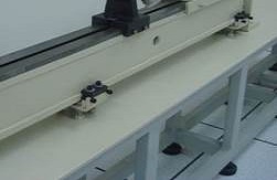 |
Base Combined Guiding rail
A combination of multiple rails that forms a unified base, with ≧ 10 meters in length. Support part of the launch system and pressure bar can work under the same basis. |
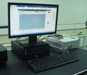
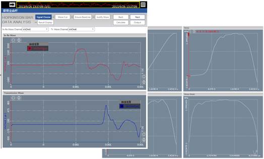
SHPB Software & Measurement
Data analysis software package features
- Preset measurement parameters
- Measurement range, sensitivity, trigger parameters , sampling rate,
- Direct control to hardware
- Channel clearing and balancing, start and stop sampling,real-time data transmitting
- Robust and powerful real-time features
- Manipulations of the channels and setting of display modes can be done dynamically
- Real-time data and waveform simultaneous display
- Powerful processing and analysis functions in time domain
- Maximum, minimum and average values, standard deviation, curve fitting, etc
- Intuitive GUI and simple guided steps to produce strain, stress, strain rate, and stress-strain curves
- Dedicated module for SHPB data analysis
- Incident-reflected, incident-transmitted, incident-reflect-transmitted methods
- Direct conversion into text, spreadsheet and image files
Result Output
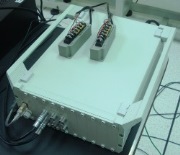
DAQ: 6-channel dynamic strain gauge system, frequency response 1MHz, amplification 3000; data processing software with built-in Hopkinson principle to quickly obtain the stress-strain curve of the specimens.
|
|